In January 2005, a few days after replacing my mini quad with a Cushcraft MA5B, the west of Scotland was hit with a major storm. The MA5B survived intact (the quad would have been decimated), but the timber mast supporting my inverted L was halved in two along with most of the garden fence. The original mast was constructed out of pieces of timber bolted together and had an nasty habit of resembling a banana after a while due to the tension of the aerial wire and the prevailing wind, so it was time to re-evaluate this part of the design.
The mark 3 antenna is electrically identical to the design I published in Practical Wireless in February 2004 and January 2005 and is designed to work on 160m, 80m, 40m, 20m, 15m and 10m and is basically half a W3DZZ tuned against earth with an extra trap and some wire for top band. The only difference is that the timber mast is replaced with a 5/8th CB mast and the wire forming the 40m element shortened to accommodate.
The astute amongst you will note that even allowing for electrical shortening normally caused by fitting traps, it still physically short for a top band antenna. This due to the linear loading effect of having the antenna quite close to the ground. If you have a higher mast and anchor point you will need a longer top band section.
The CB antenna was of unknown type and vintage and was donated to me by John MM3KNA having been obtained from him after falling off a roof during a storm (there's a pattern developing). The antenna had an external matching coil which was easily removed to change it into a unloaded aluminum rod. It is possible to just use a straight aluminum pole provided the base is insulated from earth and this method has been successfully used by Gordon MM0BIM in his version of the aerial.
The antenna works very well particularly on 40m (ZL, VK, 3B9 and Antarctica worked), on 20m you will need ATU as like the W3DZZ the impedance is high on this band. The change to the Mk3 version brings the impedance with the range of my auto ATU in my FT1000MP and will now tune on 17m and 12m as a non resonant antenna. If carefully constructed no ATU is needed for 160m 80m and 40m.
The traps are coaxial types resonate at 7.05Mhz and 3.7Mhz and details of how to makes these together with a great computer program to enable you to design coaxial traps for any HF frequency are available at Tony VE6YP's web site.
As is normal with any antenna tuned against earth, if you don't have good clay soil wire, radials are required in the ground, particularly for top band operation.
The original article can be down loaded by kind permission of Practical Wireless. Note there was error in original Top Band article in the length in the 40m section of antenna which has been corrected in this reprint.
Original  and the top band add-on
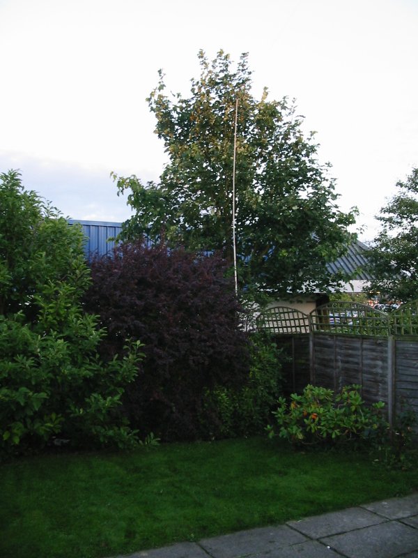
Wire 1-2mm2 enamelled copper wire obtained from an Armature Winder. Earth rod is approximately 1m long, but the longer the better. The tree to the rear looks like a suitable support, but is to thin and the top and belongs to the local supermarket next door.
|
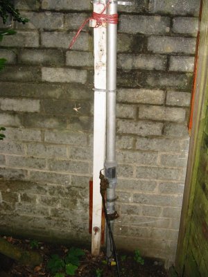
Existing cable socket covered in Denso tape to prevent dampness |
|
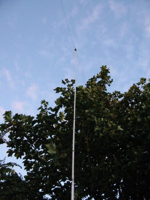
Note stay rope to rear of aerial to prevent bending |